Monday, March 31, 2014

Mastering Autodesk Maya 2013: Modeling I Cont. . . . . . .

 To Do List
  1. Add the detail on the side of the helmet.
  2. The cylinder next to the 'mic'.
  3. Extend the rails down to the shield. 
  4. The rest of the detail along the rails.
  5. Create the 'hood' on the inside of the helmet.
I told myself I was going to work in order through the list, but when I was having trouble with the detail on the inside of the helmet I broke down and did something I thought would be easier. So now the hood is already done. 

I've started on the detail on the inside of the helmet. All I have left to do is create the circular bit on top of it. 


Now I'm going to work on the cylinder next to what I like to think of as the 'mic'. 


Next steps were to extend the rail down, and to create the rest of the detail. I know for a fact that I did it differently than what was done in the book, but I still think the way I did it is nice. 


I'm loving how it looks so far. :) I know there are a few problems with it, but overall I think it works! 


To Do List
  1. Add the detail on the side of the helmet.
  2. The cylinder next to the 'mic'.
  3. Extend the rails down to the shield. 
  4. The rest of the detail along the rails.
  5. Create the 'hood' on the inside of the helmet.
Yay.

Sunday, March 30, 2014

Mastering Autodesk Maya 2013: Modeling I - Finishing the Helmet

Yesterday's To Do List

  1. Add the detail on the side of the helmet.
  2. The cylinder on next to the 'mic'.
  3. Extend the rails down to the shield. 
  4. The rest of the detail along the rails.
  5. Create the 'hood' on the inside of the helmet.

Might as well go in order. 

1. Add the detail on the side of the helmet. 

First I tried to make a nurbs patch and shape it with the vertices, but it didn't look quite right, and it wouldn't really flow with the curve of the helmet like I needed. 
FAILURE

Then I tried;
Drawing the shape onto the helmet with the cv curve tool (set to 3 cubic). 
Trimming the curve, deleting the inner part.
Duplicating the trim curve.
Group the curves. (For some reason my trim curve was separated into three different parts.)
Move and scale the duplicated curve.
Freeform Filet across the trim curve.(ERROR apparently the freeform filet does not work on two curves that are not a part of  a surface. )
I lofted between the duplicated curve and the trim curve. 

I ran into a problem because for some reason when I created the CV curve it separated  it into three separate lines, which made it impossible to fillet across. I needed it to be separated into two sections. 

The reason it is separated into three separate sections is because it's running across the seam of the nurbs circle's helmet. Which would be okay if it wasn't for the fact that when I was forming the shape of the helmet I messed up the seam.

So now the nurbs surface is slightly pulling away at the seams. It's overlapping so when I'm looking at it in shaded mode it looks fine, but when trying to work with the surface/hulls it's messing up. I spent HOURS trying to fix this issue or find a way around it.


I ended up going on spring break and took a step away from maya at this point. It turned out to be a bad idea. I left at a point I was getting extremely frustrated with and it took me a while to jump back on the horse.

Well I'm back and I've gotten some work done.

I ended up just finding a way around my little problem at this point. I'm not sure how the problem occurred nor how to fix it. Once I've finished this project I'm probably going to go through it again to see if I end up with the same problem.

What I ended up doing to get past the issue was the following


  • I drew the shape on the side where the seam wasn't getting in the way. [At this point I couldn't follow the exact steps the book seemed to have taken because my trim edge wasn't separated into two sections and I couldn't create a surface fillet]
  • I used the trim tool with the settings set to keep and keep original. This allowed me to create a copy of the surface on the inside of the trim.
  • I lofted between the trim edge and the new trim surface.
  • I duplicated the trim surface and loft and moved them to the other side of the helmet. 


So now I finally have some of the detail on the side of the helmet. 


Friday, March 14, 2014

Mastering Autodesk Maya 2013: Modeling I - Lofting & Live Surfaces

Lofting Across Multiple Curves

This section was all about how to model the tube that connects both headlights. To do this I selected the isoparm on the back of the headlight created a curve, duplicated it and scaled it -1 in the y axis to put it on the opposite side of the helmet. The two new curves were duplicated separately and rotated 50 and -50 giving me the guides for my lofts to follow. I moved the vertices around a bit to form it to the helmet. 


Live Surfaces

Next, I needed to start adding some detail to the helmet. To do this I went through a tutorial on how to use live surfaces. When you click a surface and make it live you put it into a temporary state that allows you to draw curves directly on it. I added in some isoparms to get the intended geometry correct and then made two CV curves in the shape of a square. These curves were then lofted and risen a bit to make the raised surface on the helmet. 


So here's where they left me on my own. Luckily I was able to go into their scene to kind of take a look at how they did it. 

Here's a screenshot of their helmet. As you can see I dissected it a little to see how they modeled certain parts. 


Here's how it looks without being dissected. 


I decided my first step would be to create the button like do-dads on the sides of the tube. 

To do this I used the tips provided when I 'cut' a hole in the bottom of the helmet; I created a surface intersection and then used the trim tool. I then did the same -1 in the X axis to create the same hole on the other side of the helmet. 


Next I copied the new trim edges moved/scaled them down and lofted between them. 


I then created a nice little cap for the hole. I repeated the process for similar designs along the tube. 


Next I moved onto the little mic looking parts on the helmet. This one took a couple of tries. At first I tried to model a NURBS cylinder but the caps at the ends of the caps don't really retain their shape when I scale them. So I ended up drawing a CV curve and  revolving it to get the end result.


Tomorrow's to do list

Add the detail on the side of the helmet.
The cylinder on next to the 'mic'.
Extend the rails down to the shield. 
The rest of the detail along the rails.
Create the 'hood' on the inside of the helmet.

Thursday, March 13, 2014

Mastering Autodesk Maya 2013: Modeling I - Modeling NURBS Surfaces

Okay, so I come home from work today, ready to get in some time in Maya. I open my saved scene from last night, and lookie what I found!

A tear.

Lucky me.

After a bit of research, I ended up lofting the two isoparms and attaching the loft to the main mesh. It seems to have worked but I can still kind of tell that there  is a seam.


I don't understand why it happened in the first place. Silly NURBS.

Apparently this section doesn't actually take me through a tutorial on how to model this character completely. I was given separate files that already have some parts of the suit. I'm going to do my best to make these parts on my own.

The next part I'm going to make is one of the lamps on top of the helmet. The only thing that I wasn't given step by step instructions for  was how to do the lens and the casing. The book took me through how to attach the lens to the case as well as how to make the latches around the headlight.

Making the lens and casing was relatively easy, and the rest of the headlight was mainly lofts, freeform fillets, and duplicating isoparms.


Looking good. At this point I had to save and run out of the house, hoping that I wouldn't end up with any more splits in my mesh. Luckily everything was alright when I got home.

I went in and moved the hulls and vertices around so that the brackets had more shape and the helmet was not longer reminiscent of Mickey Mouse.


Creating Rail Surfaces

In the next section I learned how to create a rail surface. As the name implies the surface that you are creating basically 'rides the rails' of two other curves that have been made. I created a CV curve, duplicated it, rotated it, and then created a BV curve in the middle to connect the two curves. The BV curve is the surface, and the two CV curves are what it will ride along. It was with this method that I created the two outter 'rails' on the top of the helmet.

After creating one rail I duplicated it and then created a loft between the two rails and created the three bumps on the top of the helmet. 


It's looking pretty good if I do say so myself. 

I really do need to work on speed eventually, but since I'm still learning I'll cut myself a break for now. I'm hoping to have this project finished within the next five days. I feel like it should be enough time granted no outside factors come into play. 


Wednesday, March 12, 2014

Mastering Autodesk Maya 2013: Modeling I - Image Plane & Modeling with NURBS

Modeling I 

Employing Image Planes

So, first things first in the modeling process, most of the time you're going to be modeling something based on concept art, or a real object, and if that's the case, it's always easier to model when you have something to trace! Usually you'll want at least a front and side view, if not also a top view.

In this chapter I will be modeling a Space Suit! It looks like it's going to be really fun to model, and I like the concept art, probably because it looks like there's a bad ass punk girl in the suit.

Here is the concept art they gave me.


I was also given a front view and side view, with less detail so that it's a little easier to model. The concept design is by Chris Sanchez, a Los Angeles based concept artist, illustrator, and storyboard artist. For more of Chris's work, visit www.chrissanchezart.com.

Side note: Because I posted his concept art and wanted to link to his site, I actually took a look at his site and apparently he has worked on a LOT of really well known stuff.  A Game of Thrones, and the Avengers. Just to name a couple. Very talented guy. Though I don't really care for his website. 

Employing Image Planes 

First I created a couple of Image Planes so that I could reference the art for my model. Until now I have been assigning hypershades of my image to a plane in the scene, which I can see the use for in certain scenarios, but I am definitely enjoying the Image Planes.


I had to set the front image to the 'Front View' image plane, and the side image to the 'Side View' image plane. I moved them around in the x and z axis' to space them away from the center.

Modeling NURBS Surfaces

I created a NURBS sphere, detached the surface along the middle, and then moved and scaled the CV's so that it would match up with the background image of the helmet.


So far, so good.

A loft creates a surface across two or more selected curves. So I selected the outer edge of the helmet and the shield and created a loft between them. I edited the loft to make it look a little more like the reference image and also did a few tweaks on the shield and the helmet.


In the next section I learned how to intersect surfaces. Basically it's like working with a Boolean, except instead of creating a difference in my first mesh it created a new curve.

In my last post I mentioned that NURBS surfaces must have four sides. Because of this, I was unable to create a Boolean, however in order to attain this effect I created the new curve on the surface and trimmed the surface. While I appear to have cut a hole in the mesh, in reality none of the parts of the surfaces were actually deleted. Rather, it made the parts invisible as if they had been deleted.


This next part actually took me a very long time, and I kept having to go back to previous saves and redoing work, which was my fault for not saving a slightly updated version after the first time I messed up, but still rather annoying.

I had to duplicate the trimmed surface, so the new circle that was cut into the helmet, and then scale it slightly larger and loft it in order to create a hard surface ring around the neck of the suit.


The neck part is still a little bit off on the sides, but for now I'm okay with that. 

Tuesday, March 11, 2014

Mastering Autodesk Maya 2013: Modeling I - Review

You may be wondering why I jumped from Introducing Autodesk Maya to Mastering Autodesk Maya before I completed the last chapters of the former. The reason is that the last six chapters of Introducing Autodesk Maya are on shading and texturing, animation, lighting, rendering, and dynamic effects. All very important aspects of Maya that I need to learn. However, I'm really more interested in practicing my modeling techniques and continuing on that track right now than I am in learning even more tools.

Mastering Autodesk Maya unfortunately only has two chapters on modeling, but I decided that I would work on those two chapters before moving on to shading and texturing. I will be going back to Introducing Autodesk Maya as soon as I complete these two chapters. 

Modeling I 

Vocab/Notes (Mostly Review) 

Polygon Geometry: A surface made up of polygon faces that share edges and vertices. 
Polygon Face: A Geometric shape consisting of three or more edges.
Vertices: Points along the edges of polygon faces, usually at the intersection of two or more edges. 
Mesh: A series of faces that share two or more vertices. 
Planar: When all the vertices of a polygon are along a single plane. 
Non-planar: When the vertices are moved to create a fold in the surface. 

According to the book it is best to keep polygon surfaces as planar as possible in order to avoid possible rendering problems, especially in game models. 

Edge: The line between two polygon vertices. 
Non-Manifold Surface: Geometry that can't be unfolded into a flat piece. 
Examples include; 
  • When two polygons share a single vertex.
  • Three polygons are extruded from the same edge.
  • Two adjacent polygons with their normals pointing in opposite directions. 

Manifold Geometry: The volume of the model is well defined, and has the following properties. 
  • Every edge belongs to two faces.
  • Every vertex is surrounded by one sequence of edges and faces.
  • Faces only intersect each other in common edges and vertexes
  • There is a material on only one side of a face. 
Face: The actual surface of a polygon. 

Smooth Polygons: 1, 2, and 3 keys preview what the mesh will look like at certain subdivisions. 1 is at the lowest, and each operation up quadruples the number of faces and,increasing the number of vertices available for modeling.

The difference between a Subdivision Surface (subDs) and the Smooth Mesh Preview (1, 2, and 3 keys), is that the subdivision surfaces allow you to subdivide a mesh to add detail only where you need it. Example: Sculpting a fingernail at the end of a finger. There is not need to add that much detail to the entire mesh if you only need it at the tip of a finger.

When converting a polygon mesh into a subdivision surfaces keep in mind the following.
  • Keep the mesh as simple as possible; converting a dense polygon mesh to a subDs significantly slows down performance.
  • You can convert three-sided or n-sided (four or more sided) polygons into subDs, but you will get better results and fewer bumps in the subDs model if you stick to four-sided polygons as much as possible. 
  • Non-manifold geometry is not supported. You must alter this type of geometry before being allowed to convert.
NURBS: Non-Uniform Rational B-Spline 

NURBS: A HISTORY
Early in the history of 3D computer graphics NURBS were used to create organic surfaces and even characters. However, now that computers have become more powerful and software has developed more advanced tools, organics and character modeling are most often accomplished using polygons and subDs. NURBS are more useful in modeling hard surfaces objects, such as cars and armor. 
All NURBS objects are automatically converted into triangles during the rendering process. You can determine how the surfaces will be tessellated (converted into triangles) before render, and can change the settings at any time to optimize rendering. Models closer to the camera can have higher tessellations than ones farther away. 
NURBS are always made of four sided patches, you cannot create a three or five-sided NURBS patch, which can limit the kinds of shapes you can make. 

Parameterization: The way in which the points along the curve are numbered. 
Uniform Parameterization: A Curve with Uniform Parameterization has its points evenly spaced along the curve. 
Chord Length Parameterization: A proportional numbering system that causes the length between edit point to be irregular. 

Bezier Curves: Use handles for editing as opposed to CVs. (Similar to Photoshop's Pen Tool?)

Apparently you can create curves in Adobe Illustrator and import them into maya. It sounds like it could come in very handy! According to the book it is most often used as a method for generating logo text. 

A single NURBS model may often be made up of numerous NURBS patches that have been stitched together. However, when stitching patches together you need to be careful to have the same number of vertices in each direction so that it is consistent. At this level of technology polygons is a faster method. 

Image Planes: Images attached to a Maya camera, which can be used as a guide for modeling or as a rendered backdrop. 

Monday, March 10, 2014

Making the Toy Airplane

Making the Toy Airplane

The lamp was incredibly fun to make, but also fairly easy. Now I'm getting started on the toy airplane that will sit on the bottom of the lamp, which will give the lamp some character!

I made sure to do step by step this time!

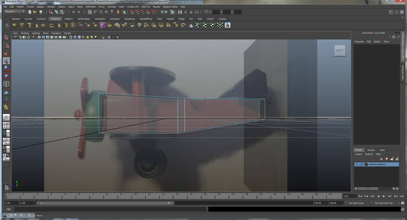
First I created reference planes and made my reference layer, so that I can basically trace the plane. By putting these images in the a new layer, I was able to set them as a reference layer and make them unselectable during the modeling process, very handy.


Next I created the 'Fuselage'

If you're like me and don't know what the heck a fuselage is, let me save you the google search.

The fuselage is the main body of an aircraft. Yay, new vocab!

I created the fuselage through boxmodeling. The two middle edges were created with the edge loop tool.


I used the interactive split tool, and the extrude tool to create the wings in the back. And moved faces and edges around in order to better shape it.


A handy trick I need to remember is that if I don't want everything in x-ray mode, and only certain objects, I can go to

Attribute Editor -> Object Display -> Drawing Overrides -> Shading

By clicking the shading box I can make is so that the object is only a wireframe. Super handy.

The following images are with the Shading turned on and off, which unfortunately doesn't really show the usefulness of this feature. This was super handy because I could  keep my reference images from being x-ray and see through my model in order to make sure everything was being modeled correctly.


Using Booleans to Finish the Fuselage

A Boolean basically takes an object, like my fuselage, and another object, like a cylinder, and uses the cylinder to create a difference in the mesh. So where the cylinder was placed in the mesh, there is now a hole in the shape of that cylinder!

Niiiice. 

I had to use this technique in order to create the space for the lamp stem, as well as to create the hole for the cockpit. 


I beveled the outer edges of the fuselage, it was slightly problematic in some areas, but overall it turned out okay. The booleans actually created a lot of problematic areas, so when I went into Mesh -> Cleanup it ended up looking like this.  It looks like I have quads and triangles in this mesh. 


Creating the Propeller and Nose


Next I created the propeller. It was separated into three parts, the cap, the propeller and the propeller button. All of which were smoothed to create nicer edges. 


Making the Wings

Easy Peasy. 


Making the Wheels

I had a bit of difficulty with this. I'm created a cv curve and then rotated it, but the only reason I got it to work out was because I used the values given from a screen shot in the book. I'm not sure I could duplicate the effect on my own. 


The plane is done! 

Using References

I just realized I forgot to post about my lamp modeling experience. Sorry! If anyone is actually interested let me know and I'll post about it. 

Last, but not least, I had to put the plane file into the lamp file. 


And the project is completed!!

The main issues with the lamp are that the trim isn't quite perfect and when I go in to add the hypershades I'll probably need to edit them a little so that the lamp shade isn't poking out in certain spots. In grey scale it looks great! 

I think the project turned out rather well. The plane had a few hiccups with the Booleans and  edge loops in combination with the bevel, but after clean up it SHOULD all be okay. . . hopefully. 


Sunday, March 9, 2014

Introducing Autodesk Maya 2013 Chapter 5: Building a TeaKettle

I love learning Maya, but the times that I have the most fun is when I'm actually modeling something worthwhile and slightly challenging. I dislike the side projects that just teach me some of the tool because I'm not coming out of the learning experience with something tangible.

Which is why I enjoyed making this Teakettle! Creating it used most of the tricks and techniques taught through the earlier parts of this chapter, as well as giving me a finished product. The Teakettle.

Unfortunately I didn't take progress photos like I should have, but here is the finished product!


Overall, I like how it turned out! 

Things I could fix
The back looks a little deformed
The spout is a little short
The handle looks a little. . . big? 

Saturday, March 8, 2014

Introducing Autodesk Maya 2013 Chapter 5: Side Projects

The rest of chapter five took me through some of the Deformer Tools that maya has to offer.

I didn't take any screen shots due to the fact that I went through the parts pretty quickly and it kind of slipped my mind, but I learned how to use the Bend Deformer so that I can 'bend' object. It would be very useful in creating tubes on a space suit, or pipes in a city, among various other projects.

I also learned about the Flare Deformer which as the name suggests, allows me to flare objects out. Which will come in handy for tweaking objects to get the shape I want.

Next I learned how to use a Lattice Deformer

The book has a model hand ready for me to work with.


So what I did was I created a Lattice which allows me to choose points on the lattice and deform the entire hand with those points.


In this project I was to deform the hand with lattices to create a hand that looked more Alien. In order to do this I created a lattice around the entire hand to elongate it, and then individually placed lattices around the fingers in order to individually shave the fingers to make them look more alien.

This is a great tool if you want to make tweaks to a project without having to go through and individually select vetices, faces, or edges. In addition to being easier, depending on what effect you're trying to achieve, it's also much cleaner. Often when working with individual vertices my project gets a little messy. When using a lattice your model remains clean.


This is what I ended up with. I'm not extremely happy with it, but I wasn't really trying for perfection as much as I was just playing around with the tool to see what it could do. If I did it again I'd put more time into and definitely put a little more effort into the thumb.

Overall I wasn't too impressed with the lattice. I could see how it would be useful later on down the road for editing pre-existing models, or for tweaking them, but it wasn't all that fun to learn.

Until the next section.

In this section I learned about Animating Through a Lattice. 

I was instructed to create the effect of a balloon squeezing through a tube. In order to create this effect I created a lattice for the 'Balloon', a simple poly sphere, and then moved it over to the tube, an open ended cylinder, I had to edit the lattice so that it was flared on the ends and squished down in the middle to form to the tube.

This is the effect it produced. 


Can you tell I had a bit too much fun with this part? It was a blast to make 'swooping' sound effects as I moved the ball through the tube.

 Ah, the simple things in life.

Last but not least I created a starfish. I created a polygonal star and then used subdivisions to create the 'star fish'. I really don't like how mine turned out, and I also didn't really enjoy working with subdivisions. Which leads me to believe I didn't understand them as well as I should have. I'm going to have to go back to them to practice them some more.

Here's my finished product.